TECHNOLOGY
About Design
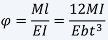
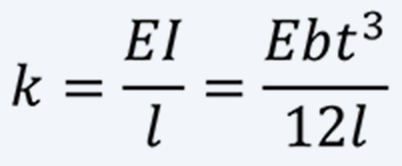
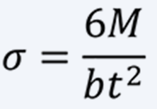
List of symbolsThe symbols used in the design methods are shown below.
- φ
- Deflection angle
- M
- Torque
- l
- Spring length
- I
- Moment of inertia
- E
- Young’s modulus
- b
- Spring width
- t
- Spring thickness
- k
- Spring constant
- σ
- Stress
- Mv
- Mass
- χ
- Radius
- T
- Period
- N
- Number of revolutions
- d1
- Shaft radius
- D2
- Case radius
- Rn
- Natural radius
- R1
- Driven shaft radius
- R2
- Drive shaft radius
- P
- Force
1Non-contact type spiral spring
i. Non-contact type spiral spring
a. Spring with many turns and fixed support at outer end
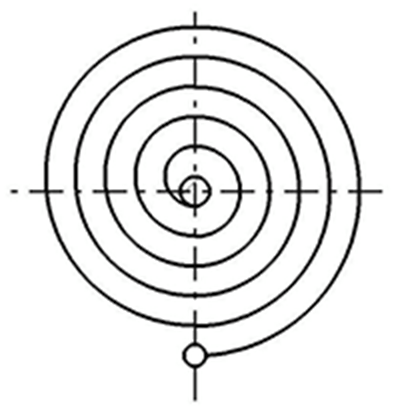
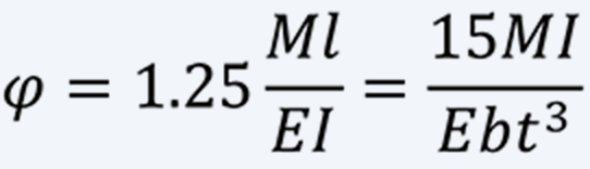
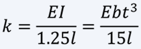
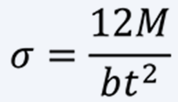
Fig. 1 shows a non-contact type spiral spring with a large number of turns, with the outer end fixedly supported and the inner end attached to the winding core. The design formulas are as follows.
-
(1) 
-
(2) 
-
(3) 
b. Spring with many turns and pinned outer end
In case of a spring with pinned outer end by a pin joint or the like, the calculation formulas are as follows.
-
(4) 
-
(5) 
-
(6) 
Since no moment acts on pinned outer end, the deflection angle is about 25% larger than that of a spring with fixed outer end. In addition, the bending stress is not the same over the entire spring, and the position of maximum bending stress is near the outer end. When same torque is applied, the bending stress of a spring with pinned outer end is twice as large as that of a spring with the outer end fixedly supported.
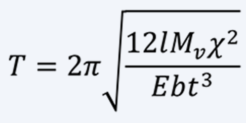
ii. Hair spring
A hair spring is a kind of small non-contact type spiral springs with many turns, but it has a special characteristic, isochronism. It is necessary to be designed to reduce the eccentricity between the center of rotational vibration and its center of gravity. Details of the design method of hair spring are omitted here.
Assuming that the mass of the vibrating body is Mv and its radius of gyration is χ, the period T of the vibrating body is as follows.
-
(7) 
2Contact type spiral spring
i. S-shaped spiral spring
A spiral spring that undergoes primary winding process and has a free shape similar to an S-shape is called S-shaped spiral spring.
a. Number of revolutions and spring length
The total number of revolutions is maximized when the sagittal area of the spring, spring plate thickness multiplied spring length, is equal to 1/2 of the area that obtained by subtracting the cross-sectional area of the shaft from that inside the case. Then, the total number of revolutions N is as follows, assuming that the spiral spring with no torque applied is in close contact with the case and ignoring the close contact winding part with the shaft.
-
(8) 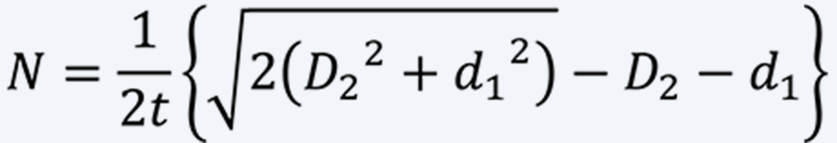
However, in practice, a spring length that meets the total number of revolutions required is often selected.
b. Torque characteristics and stress of a spiral spring
In the S-shaped spiral spring, compressive stress is applied to the outside of the plate as initial stress. The relationship between torque M and stress σ is as follows.
-
(9) 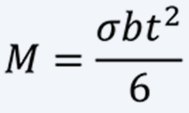
Stress σ in this case is the sum of initial compressive stress and tensile stress caused by spring deformation. The spring constant k, which is linear characteristic of torque obtained when the entire spring is evenly loaded, is as follows.
-
(10) 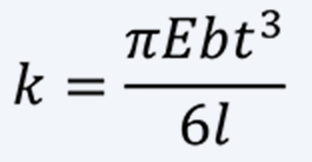
Since only a part of the spring characteristics can be calculated with these formulas, it is necessary to perform numerical analysis for practical design.
ii. Spiral spring without primary winding process
The design formulas for the spiral spring made by winding a straight steel strip is the same as that for the S-shaped spiral spring.
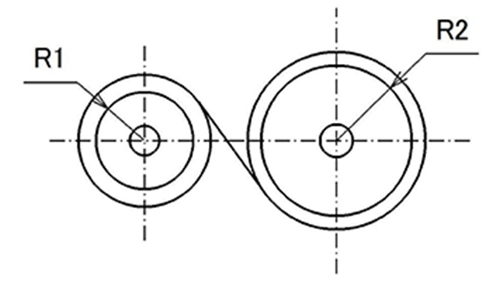
iii. Constant torque spring
A constant torque spring is a spring that is tightly wound a natural radius Rnsub when no torque is applied, and is attached to a driven shaft with a radius slightly larger than Rnsub, and its free end attached to the drive shaft. It works by rotating the drive shaft in the same direction as the driven shaft or in the reverse direction. The characteristic of constant torque spring is that torque is almost constant regardless of the number of revolutions. Torque at any number of revolutions can also be changed by changing Rnsub. Furthermore, it is easy to secure the number of revolutions.
However, stress amplitude of a constant torque spring is large and the durability is generally low.
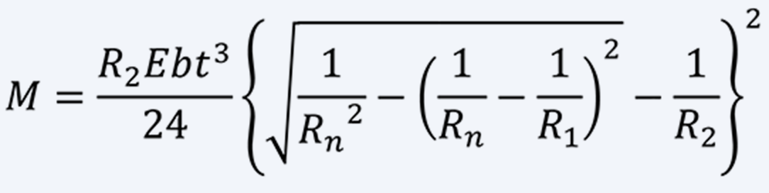
a. A-motor
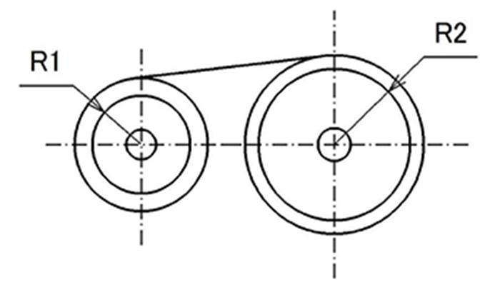
A constant torque spring in which the drive shaft and driven shaft rotate in the same direction is called an A-motor.
Torque M of A-motor is as follows:
-
(11) 
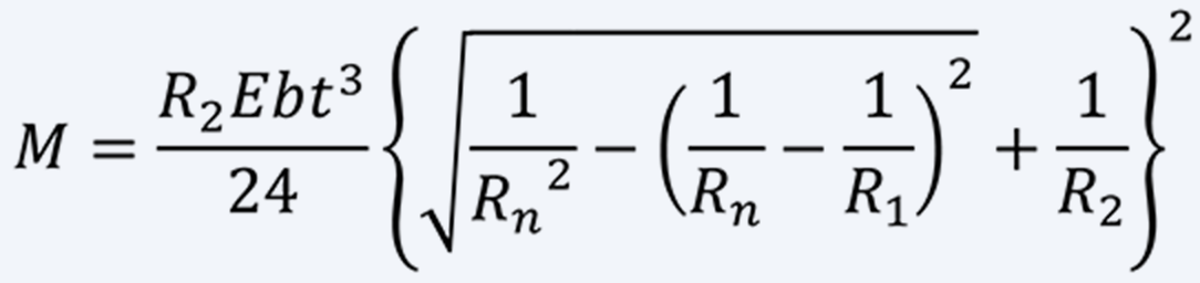
b. B-motor
A constant torque spring in which the drive shaft and driven shaft rotate in the opposite direction is called a B-motor.
Torque M of B-motor is as follows:
-
(12) 
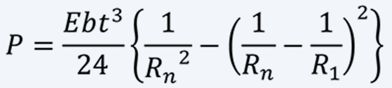
iv. Constant force spring
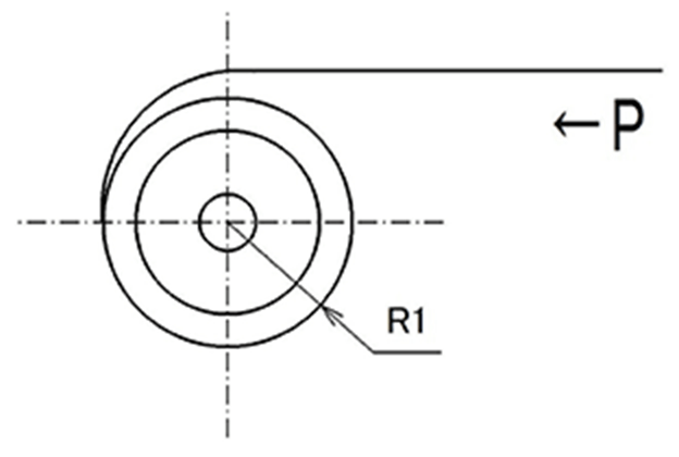
Similar to a constant torque spring, a spring that pulls out the outer end linearly and utilizes the entrainment force is called a constant force spring.
Force P in this case is almost constant regardless of spring stroke and is as follow.
-
(13) 
3How to design stress
In the case of a spiral spring, the maximum stress during use is near the yield point of the material, but when discussing durability performance, the focus is on how to design stress amplitude (stress range). From Eq (9), it is possible to infer to some extent from the difference in maximum torque and minimum torque. However, spiral spring actually has some area in close contact with the case or shaft during use, and stress amplitude in that contact area is low, and the stress amplitude in other area is large. Therefore, it is necessary to calculate stress amplitude by numerical analysis.
4Design notes
When designing a spiral spring that doesn’t perform primary winding process, a spring wound from straight steel strip plastically deformed in most areas and becomes spiral shape when no torque is applied. However, if spring length is too long, plastic deformation does not occur in some areas, and spring material in that area remains straight shape. Since this area causes the same deformation at the same moment, the friction between the plate increases and the behavior of the spring is worse. Note that the torque and the durability may decrease.
5Design example
As mentioned above, the formula can only derive an outline of a contact type spiral spring design.
i. Design example of a spiral spring
Design a spring with a range of use of 10 revolutions and a minimum torque M of 100 [N・mm]. The material is SUS301, the inner diameter D2 of the case is 50 [mm], a shaft diameter d1 of 10 [mm], and a plate width b is 8 [mm]. First, assume that the maximum torque Mmax of a spring is 150 [N・mm]. If a spring is S-shaped, the maximum stress σmax is about 2400 [MPa] (Without primary winding σmax = 1800 [MPa]) .The plate thickness t is 0.220 [mm] from (9).
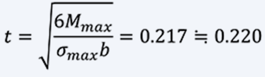
Assume that the total number of revolutions is 22, the maximum torque in this case is Mmax = 155 [N・mm].
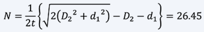
Assume that the annealed part at the inner end is provided with 1.5 turns, that is, 50 [mm], it can be tightly wound around the shaft. At this time, the shaft diameter is considered to be as follows in calculation:

From Eq (8), the total number of revolutions N is:
The length of a spring l is:
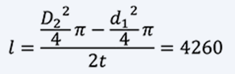
Assume that a spring is in close contact with the case when no torque is applied. The total number of turns is the difference between the number of turns when it is tightly wound around the shaft and the number of turns when it is in close contact with the case:
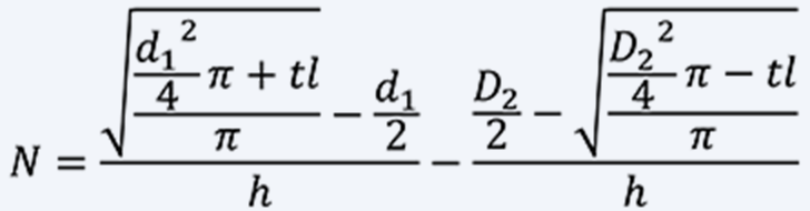
Assume that the total number of turns is 22, l = 2160 [mm].
The spring constant is calculated from Eq (10), where Young's modulus E is 190 [GPa]:
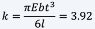
If the usage range is N = 8 ~ 18:


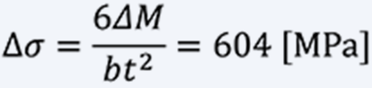
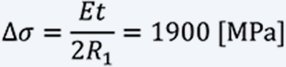
The stress range ∆σ is: *
- * For a material with a rectangular cross section, such as a spring, where the width is larger than the thickness, EI⁄((1-v^2 ) ) instead of EI gives more accurate results.
- * Based on our data, ∆σ≒600 [MPa] is a guideline for durability that can withstand 100,000 times of use.
ii. Design example of constant force spring
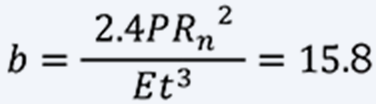
Design a constant force spring with a pull-in force of P=10 [N]. The constant force spring is used by stretching a coiled thin plate in a straight line. No matter how small the thin plate is coiled, if it is stretched in a straight line, it will undergo plastic deformation, that is, there is a limit to setting Rn. The limit depends on the material, but 40 times the plate thickness is a guide.
Now, in Eq (13), if the plate thickness is t = 0.200 [mm], the coiling radius Rn that can be make is Rn≧8. If Rn = 10 [mm], Young's modulus is 190 [GPa], and the driven shaft radius is 10 [mm], the plate width b is:
The stress range ∆σ at this time is:
Based on our data, it is a performance that can withstand about 15,000 [cycle].